Elegoo Neptune 4 Hardware
Note: This is a work-in-progress. Right now, it mostly describes the control board, screen, and related items.
Specifications
Mostly taken from the product descriptionon Elegoo’s website.
| Feature | Description |
|---|---|
| Print volume | 225mm x 225mm x 256mm |
| Print speed | 30-500mm/s (250mm/s suggested) |
| Auto-leveling* | 11 x 11 |
| Nozzle† | 0.4mm brass, 300°C max |
| Materials‡ | PLA, PETG, ABS, TPU, Nylon, Wood, Marble, etc. |
| File Transfer | USB, LAN |
| Firmware | Klipper |
| Extruder | Dual-Gear, 5.2:1 reduction |
| Heat Break§ | Copper-Titanium |
| Print Surface | 235x235mm PEI-coated magnetic spring steel |
| Cooling | 2x 4015 blowers (tool), 4x 4020 fans (x-axis) |
| Screen | 4.3-inch capacitive touch |
| Lighting | Tool LEDs, Gantry LED strip |
| Frame Material | Aluminum extrusion (various) |
| Technology | FDM |
| Rated Voltage | 100/240V 50/60Hz |
| Overall Dimensions | 475x445x515mm |
| Max Nozzle Temperature | 300°C |
| Max Bed Temperature | 110°C |
| Supported Formats | .stl, .obj, .amf |
| Supported Languages | English, French, German, Russian, Italian, Spanish, Japanese, Chinese |
| Resume Printing | Yes |
| Filament Detection | Yes |
| Net Weight | 8.3Kg |
* This is the default value, but configurable in Klipper
† Elegoo does not currently sell other sizes/materials. However, they can be found on AliExpress
‡ Abrasive materials not recommended with the included brass nozzle
§ This may be misleading, as the extruder feeds a PTFE tube, which feeds the throat-pipe
Dimensions
Given dimensions should be accurate-enough, but further measurements are a work-in-progress.
Board
| Dimension | Size |
|---|---|
| Length | 140mm |
| Width | 90mm |
| Diameter, Screw Hole | 4mm |
| Inset, Screw Hole | 4mm |
| Screws | M3 8mm pan-head Phillips plastic/wood |
| Standoff Height | 6mm |
Screen
Panel measurements were from specifications in the product listing on AliExpress. Other measurements were performed in-place.
| Dimension | Size |
|---|---|
| Length | 145mm |
| Width | 87mm |
| Depth | 20mm |
| Panel | |
| Length | 105.5mm |
| Width | 67.2mm |
| Depth | 3mmm |
| Board | |
| Length | 82mm |
| Width | 28.5mm |
Wires
INCORRECT WIRE SIZING IS A FIRE HAZARD! If you intend to replace any of the wiring, check the sizes on your unit. These are provided for reference only, and some are approximations due to insufficient labeling on some cables.
| Connection | Size, mm | Size, AWG |
|---|---|---|
| Power Supply | 1.5 | 15 |
| Bed Heater | 1.5 | 15 |
| Bed Thermistor | 0.5 | 24 |
| Model Fan | 0.5 | 24 |
| Frame LED | 0.5 | 24 |
| Filament Detector | 0.5 | 24 |
| Axis Ribbon Cables | 0.5 | 24 |
| Control Board Fan | 0.4 | 26 |
| Tool Ribbon Cable | 0.4 | 26 |
The axis ribbon cables includes conductors for each axis, and the associated endstop (X, Y only).
The tool ribbon cable includes conductors for:
- Hotend Heater Cartridge: 3x wires, equivalent to 0.72mm (21 AWG)
- Hotend Thermistor
- Extruder Stepper Motor
- Fans (3x)
-
LED
- Proximity Sensor
The heater cartridge runs at 24 V, 50 W (2.08 A). Just one of the conductors should be able to safely carry the current over the given distance, so three provides a good safety margin. However, if you need to replace these, it would be highly-advised to use the same size wire as the heater cartridge leads.
Nozzle
The Neptune 4 uses a non-standard nozzle. It is very close to the RepRap style of nozzle, except the threaded length is 2mm longer, the overall length is 5.5mm longer, and the nozzle profile is slightly different.
| Dimension | Size |
|---|---|
| Overall Length | 18mm |
| Thread | M6 x 1, 9mm |
| Hexagonal Surface | 6mm x 4.5mm |
Heat Block
| Dimension | Size |
|---|---|
| Width | 20mm |
| Depth | 16mm |
| Height | 15mm |
| Nozzle/Break Thread | M6x1 |
| Mounting Screw Holes | 5.25mm x 13.2mm, 2.5mm x 1.8mm |
| Mounting Screw Holes Position | 7.5mm from center, 3.125mm from rear |
| Mounting Screws | M2x0.25, 10mm, 1.5mm hex cap-head |
| Heat Cartridge Diameter | 6mm |
| Heat Cartridge Set Screw | M3x0.5 |
| Thermistor Hole | 3mm x 10mm |
| Retention Screw | M3x0.5, 4.25mm, 2mm hex round-head |
Heat Break
The heat break is nearly identical to Slice Engineering’s Copperhead Heat Break, C-E variant. This means heat breaks intended for similarly-equipped Creality printers should also be close.
The main difference is the distance between the shank and the threaded portion (air gap), which is 1mm longer on the Neptune 4. The threaded length on the Neptune 4 is correspondingly 1mm shorter.
Because of this, using the Copperhead heat break may work, but there could be a higher risk of heat creep.
| Dimension | Size |
|---|---|
| Overall Length | 28mm |
| Shank Length | 20mm |
| Shank Outer Diameter | 7mm |
| Shank Inner Diameter, Top | 4.15mm |
| Shank Top Depth | 5mm |
| Tube Outer Diameter | 2.5mm |
| Tube Inner Diameter | 2mm |
| Air Gap | 2.5mm |
| Thread | M6 x 1, 5.5mm |
Heatsink
| Dimension | Size |
|---|---|
| Width | 35.5mm |
| Fin Depth | 16mm |
| Top Depth | 9.88mm |
| Overall Height | 24.15mm |
| Fins Height | 17.15mm |
| Top Height | 7mm |
| Tube Hole Top | 4mm x 6mm |
| Tube Hole Bottom | 7mm x 18.15mm |
| Tube Hole Position | Centered, 5.5mm from rear |
| Mount Holes | 3.5mm |
| Mount Holes Position | 2.25mm from top, 4.75mm from side |
Details
Controller Board
| Component | Detail |
|---|---|
| SOC | RK3328 |
| RAM | 8GB DDR3 933 M15T4G16256A–DEBG2[S/C] |
| Storage | KLM8G1GETF-B041 eMMC |
| Microcontroller | STM32F402RCT6* |
| Drivers | TMC2209 |
| Serial Adapter | CH340C |
* The STM32F402RCT6 seems to be identical to the STM32F401RCT6, according to their respective datasheets (STM32F401RC, STM32F402RCT6) and other available English-language information.
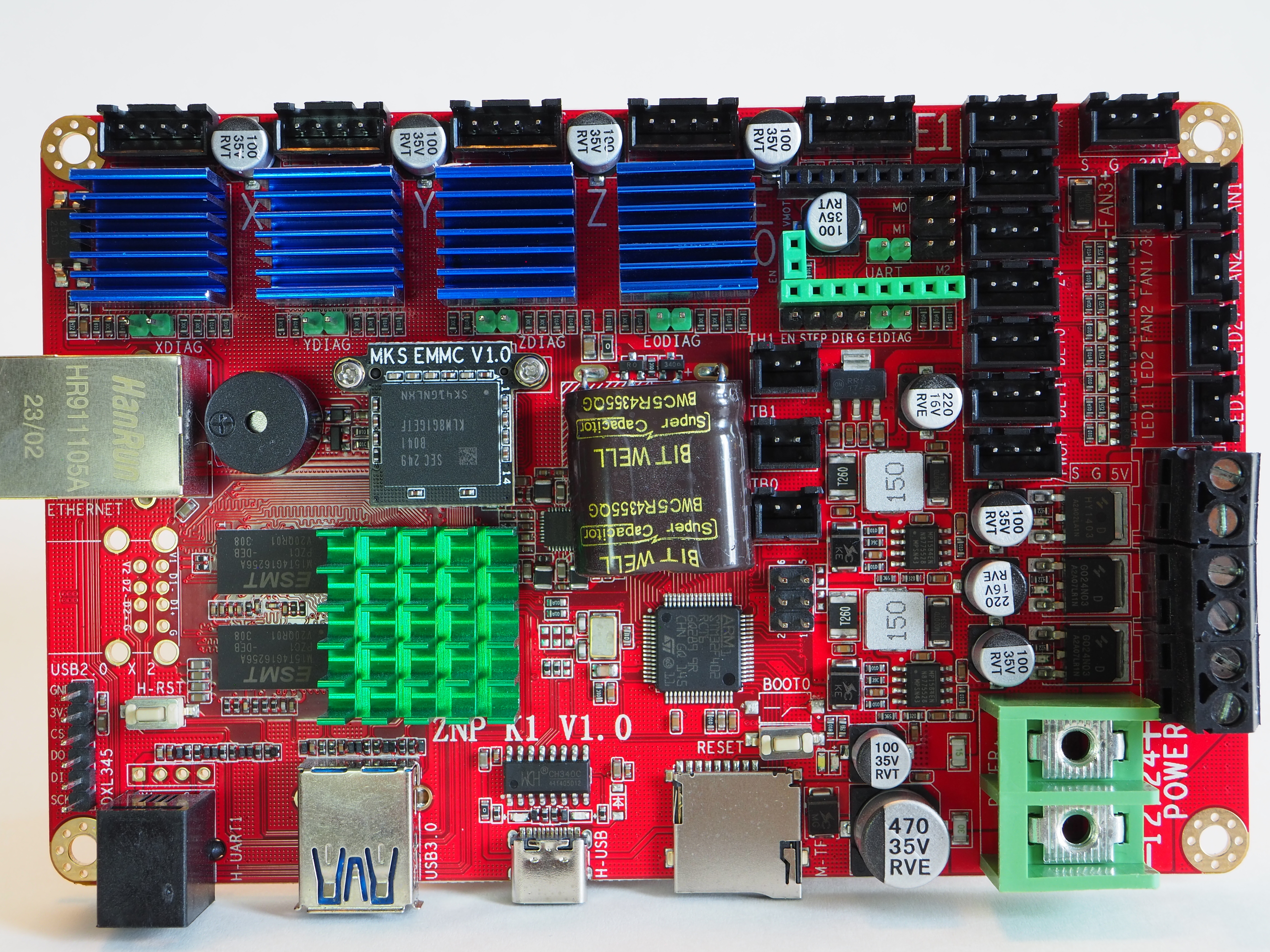
The Neptune 4 uses a ZNP K1 v1.0 control board. There is not much information on this exact board, aside from a brief overview in the article Elegoo Neptune 4 3D Printer in Review. A comment on the Reddit post Am I crazy or is the Neptune 4 (Pro) just not a great deal?, claims it is a clone of the MKS Skipr. However, there are some significant differences between the two.
Interfaces
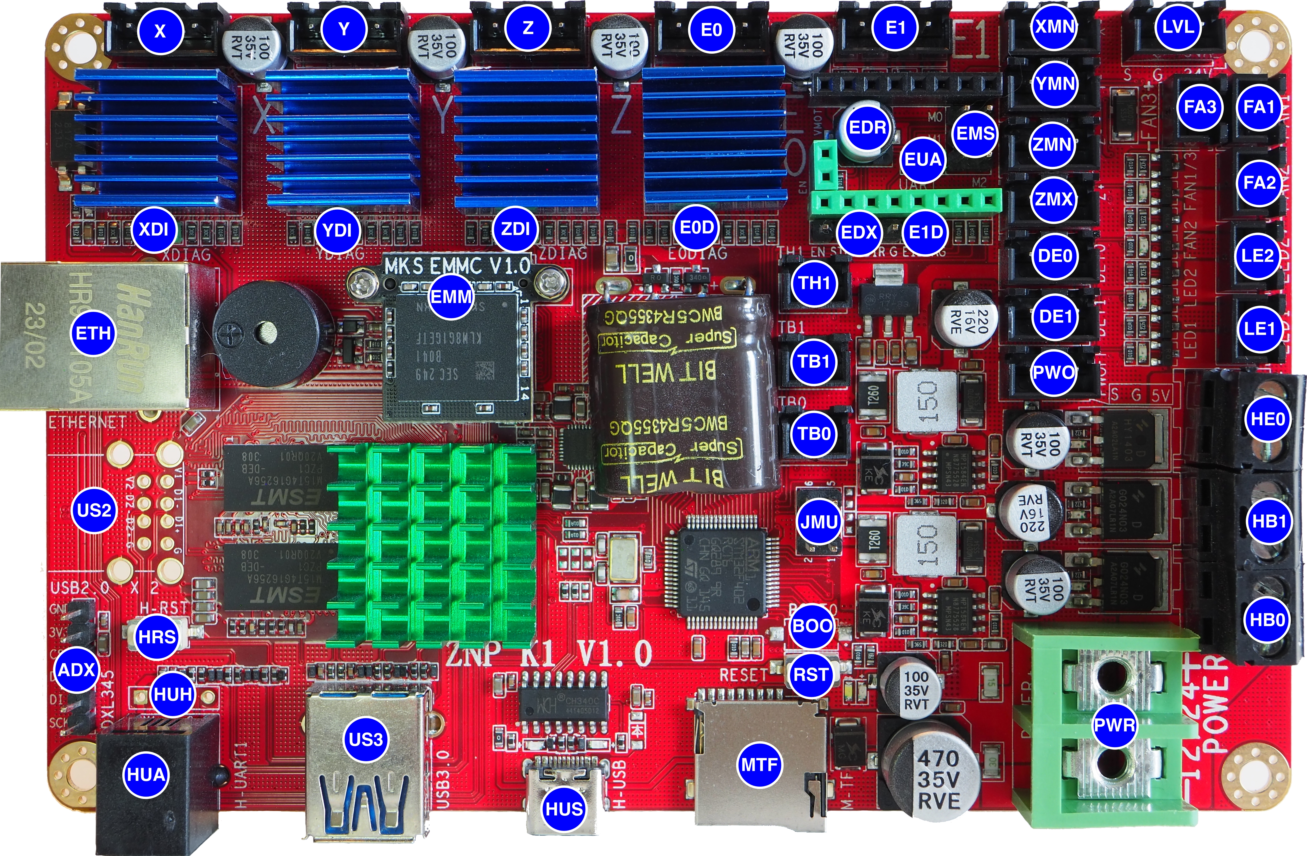
| ID | Board Text | Description |
|---|---|---|
| Fans/LEDs | ||
| LE1 | LED1 | Model Light |
| LE2 | LED2 | Frame Light |
| FA1 | FAN1 | Tool Fan(s) |
| FA2 | FAN2 | Model Fan |
| FA3 | FAN3 | Control Board Fan |
| Ports | ||
| ETH | ETHERNET | 10/100/1000 Ethernet |
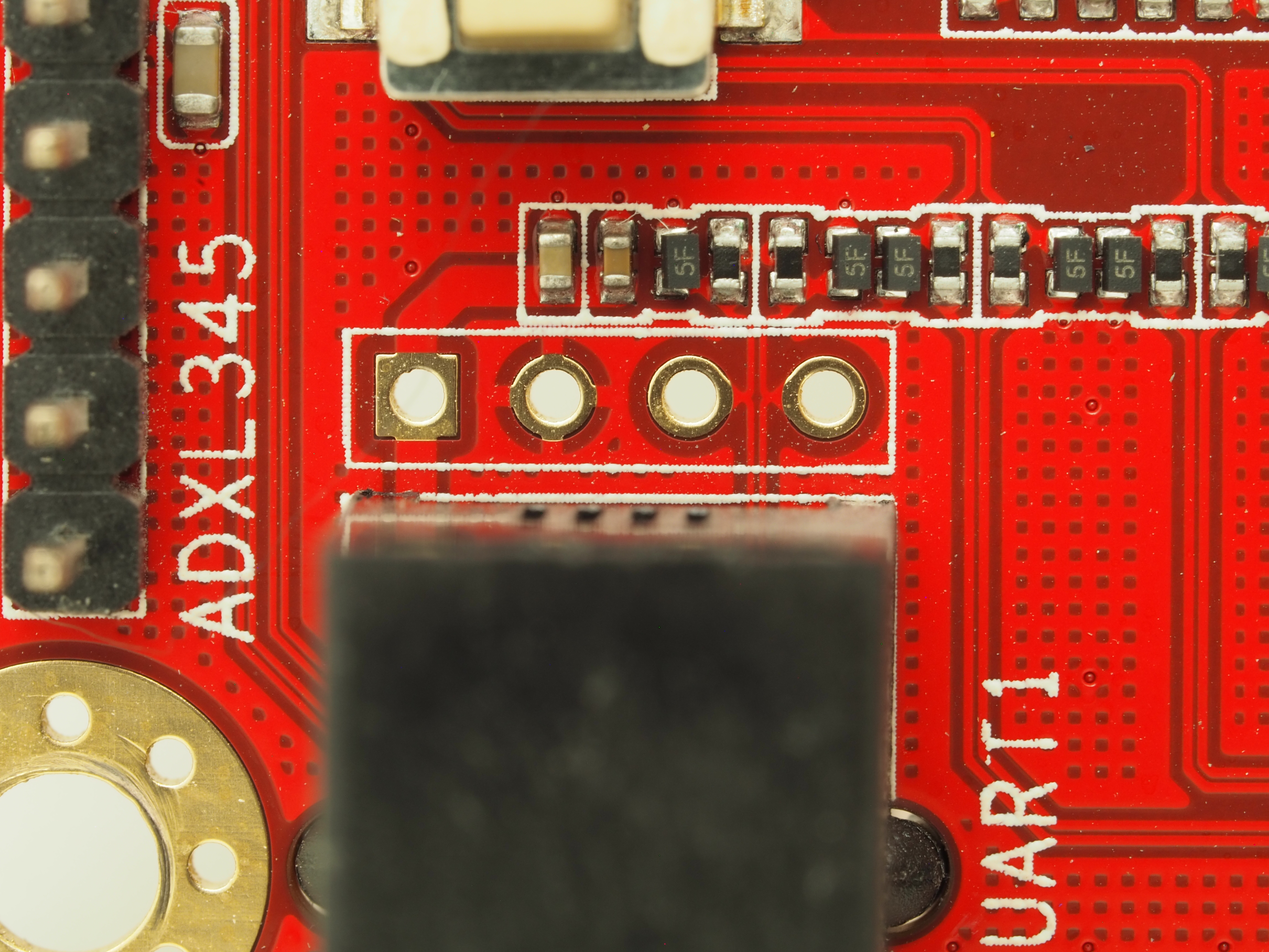
| US2 | USB2.0 X2 | USB 2.0, Unpopulated |
| ADX | ADXL345 | ADXL345 Accelerometer |
| HUA | H-UART1 | Screen UART Interface |
| HUH | Header for UART Screen Interface, Unpopulated | |
| US3 | USB3.0 | USB 3.0 Port |
| HUS | H-USB | USB-C Port, Internal Serial Adapter Only |
| MTF | M-TF | MicroSD Card Reader, MCU Only |
| Power | ||
| PWR | 12/24 POWER | Power Supply |
| HE0 | HE0 | Hotend Heater |
| HB0 | HB0 | Hotbed Heater 0 |
| HB1 | HB1 | Hotbed Header 1 |
| Sensors | ||
| XMN | X- | X Minimum Endstop |
| YMN | Y- | Y Minimum Endstop |
| ZMN | Z- | Z Minimum Endstop |
| ZMX | Z+ | Z Maximum Endstop |
| DE0 | DET0 | Filament Runout Detector 0 |
| DE1 | DET1 | Filament Runout Detector 1 |
| PWO | PWOFF | Power Off Trigger |
| TH1 | TH1 | Hotend Thermistor |
| TB0 | TB0 | Heatbed Thermistor 0 |
| TB1 | TB1 | Heatbed Thermistor 1 |
| LVL | Level/S/G/24V | Proximity Sensor (Leveling Probe) |
| Steppers | ||
| X | X | X Stepper |
| Y | Y | Y Stepper |
| Z | Z | Z Stepper |
| E0 | E0 | Extruder 0 |
| E1 | E1 | Extruder 1 |
| EDR | VMOT/EN | Extruder 1 Driver Polou Board |
| EUA | UART | Extruder 1 UART Mode Jumper |
| EMS | M0/M1/M2 | Extruder 1 Microstep Mode Jumper |
| EDX | EN/STEP/DIR/G | Extruder 1 External Driver |
| XDI | XDIAG | X Sensorless Homing Jumper |
| YDI | YDIAG | Y Sensorless Homing Jumper |
| ZDI | ZDIAG | Z Sensorless Homing Jumper |
| E0D | E0DIAG | Extruder 0 Sensorless Homing Jumper |
| E1D | E1DIAG | Extruder 1 Sensorless Homing Jumper |
| Misc | ||
| EMM | EMMC | EMMC Board |
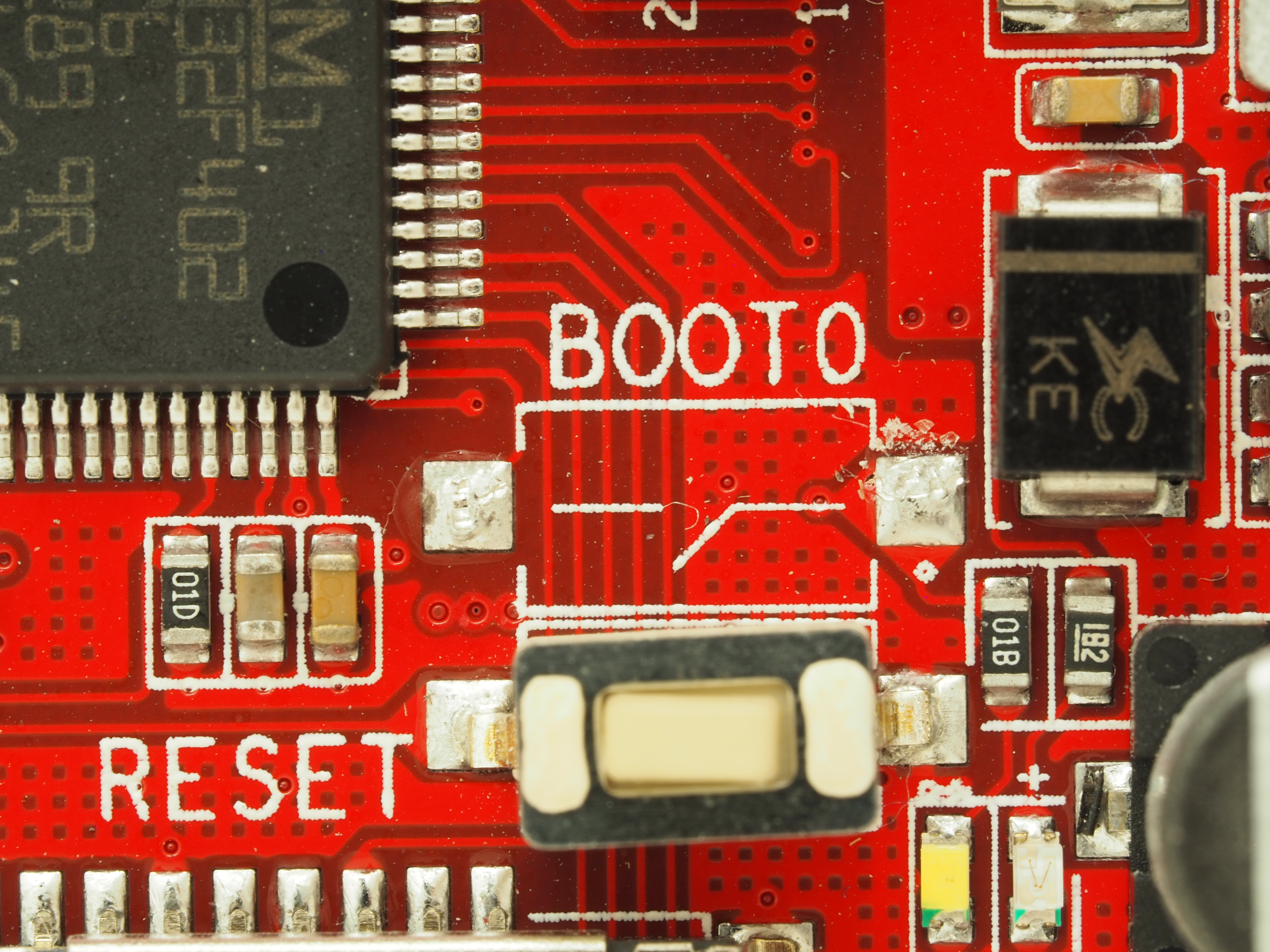
| BOO | BOOT-0 | BOOT-0 Mode Select |
| RST | RESET | MCU Reset |
| HRS | H-RST | Host Reset |
| JMU | 1/2/5/6 | Mode Select Jumpers, Unused |
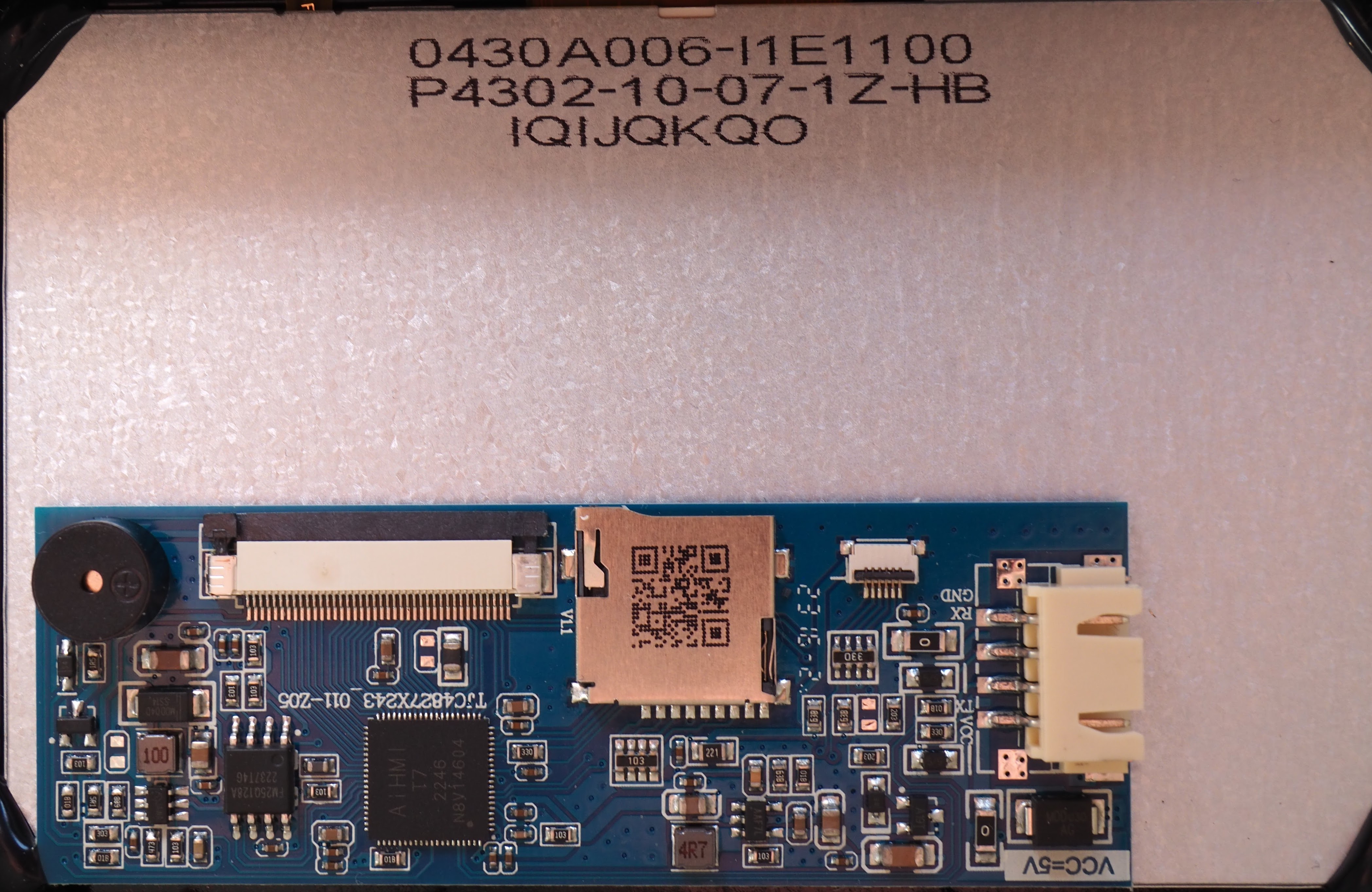
Screen
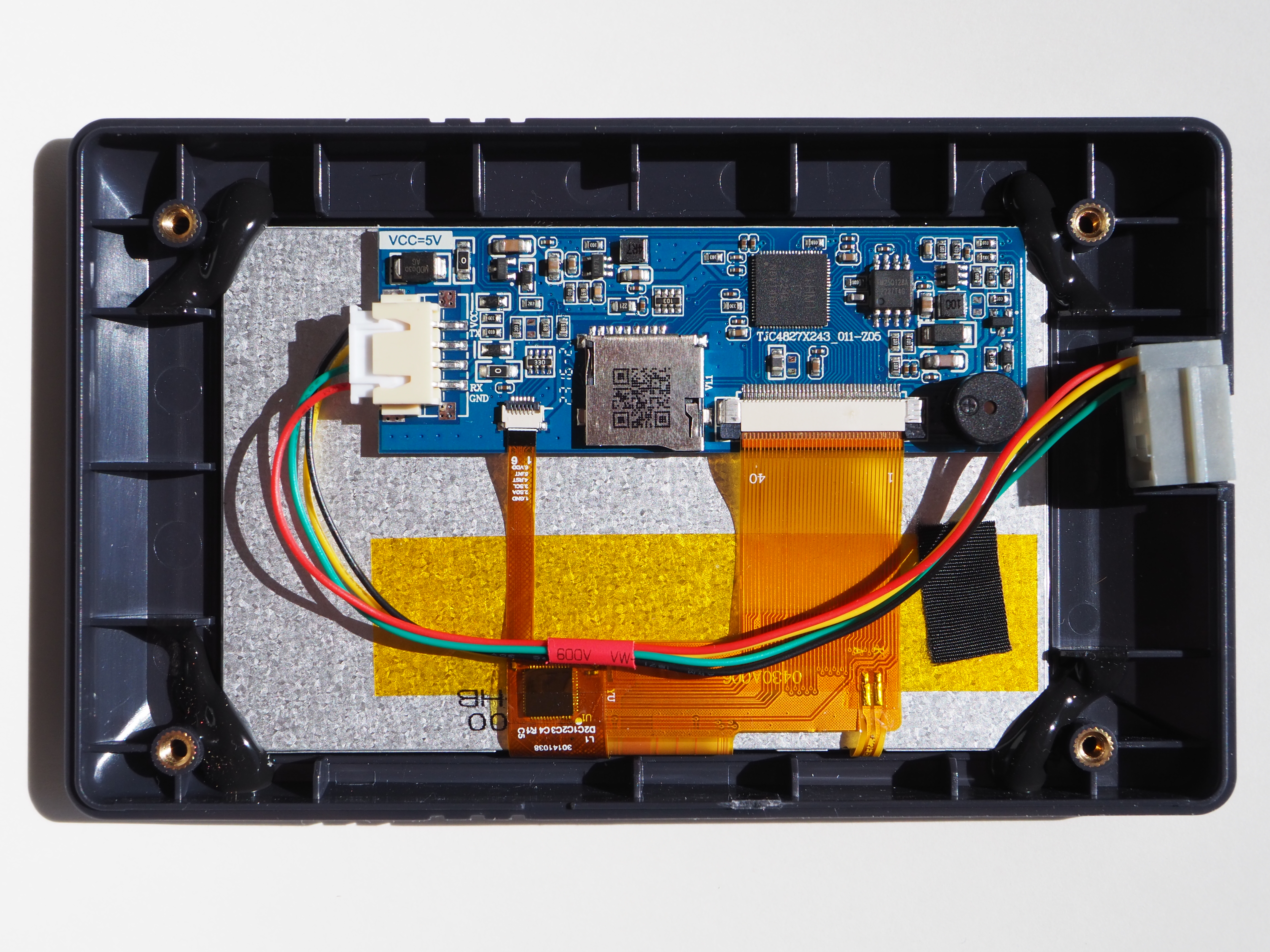
| Component | Detail |
|---|---|
| Board | Tenlog TJC4827X243_011-Z05 |
| Panel | 0430A006-I1E1100 |
| Digitizer* | Goodix GT911 (Datasheet) |
* This is a guess based on other, similar configurations from the same manufacturer.
Variants of this board/screen combination are found for sale are advertised as being for the Tenlog TL-D3 Pro/D3-V2/TL-D5/TL-D6 printers, although some similar screens are used in Creality printers. It is plausible that these are being manufactured by/for Tenlog and whiteboxed for other manufacturers.
It is likely that there are, or will be, many interchangeable variants that will crop up in the Neptune 4 as production continues, so the specific details will change.
Board
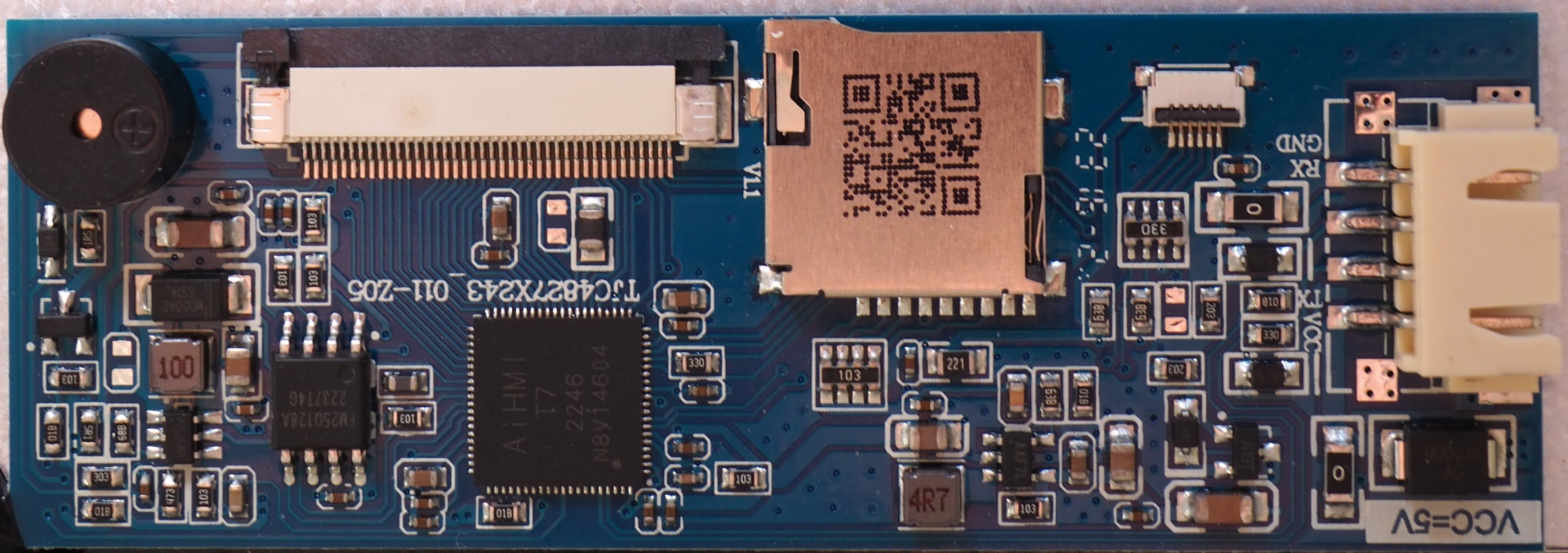
| Component | Detail |
|---|---|
| Microcontroller | Unknown, “AiHMI T7 2246 N8V14604” |
| Flash Memory | FM25Q128A 128MB SPI NOR Flash (Datasheet) |
| EEPROM* | 1KB |
| RAM* | 512KB |
| Serial Command Buffer* | 4KB |
* These values were taken from a listing for a similar board, but not verified.
This appears to be identical to other TJC4827X243_011-xxx variants, except for the board configuration, so presumably the last 3 characters likely indicate a board revision.
The QR-code on the micro SD card reader contains the following text:
hxe5hse5xse494e516v1.65
Panel
These specifications were taken from product listings for this panel and other equivalent ones from the same manufacturer.
| Feature | Detail |
|---|---|
| Type | LCM |
| Size | 4.3-inch |
| Aspect Ratio | 16:9 |
| Manufacturer | BOE |
| Dimensions | 105.5mm x 67.2mm x 3mm |
| Active Area | 95.04mm x 53.86mm |
| Resolution | 480 x 272 |
| LCD Type | a-Si TFT, TN |
| Viewing Direction | 12 o’clock |
| Driver IC | ILI6485 |
| Operating Temperature | -20°C — 70°C |
| Storage Temperature | -30°C — 80°C |
| Backlight | 10x LED |
| Brightness | 200 nit |
| Working Voltage | 4.65V — 12V |
| Working Current | 220mA |
| Sleep Current | 100mA |
The module was manufactured by Shenzhen Hong Xian Wei Ye Technology Limited, and customized to include a capacitive touch digitizer. The base panel assembly is the 0430A006-I1E1100. The LCD panel was made by BOE, but the exact model is currently unknown.
Digitizer
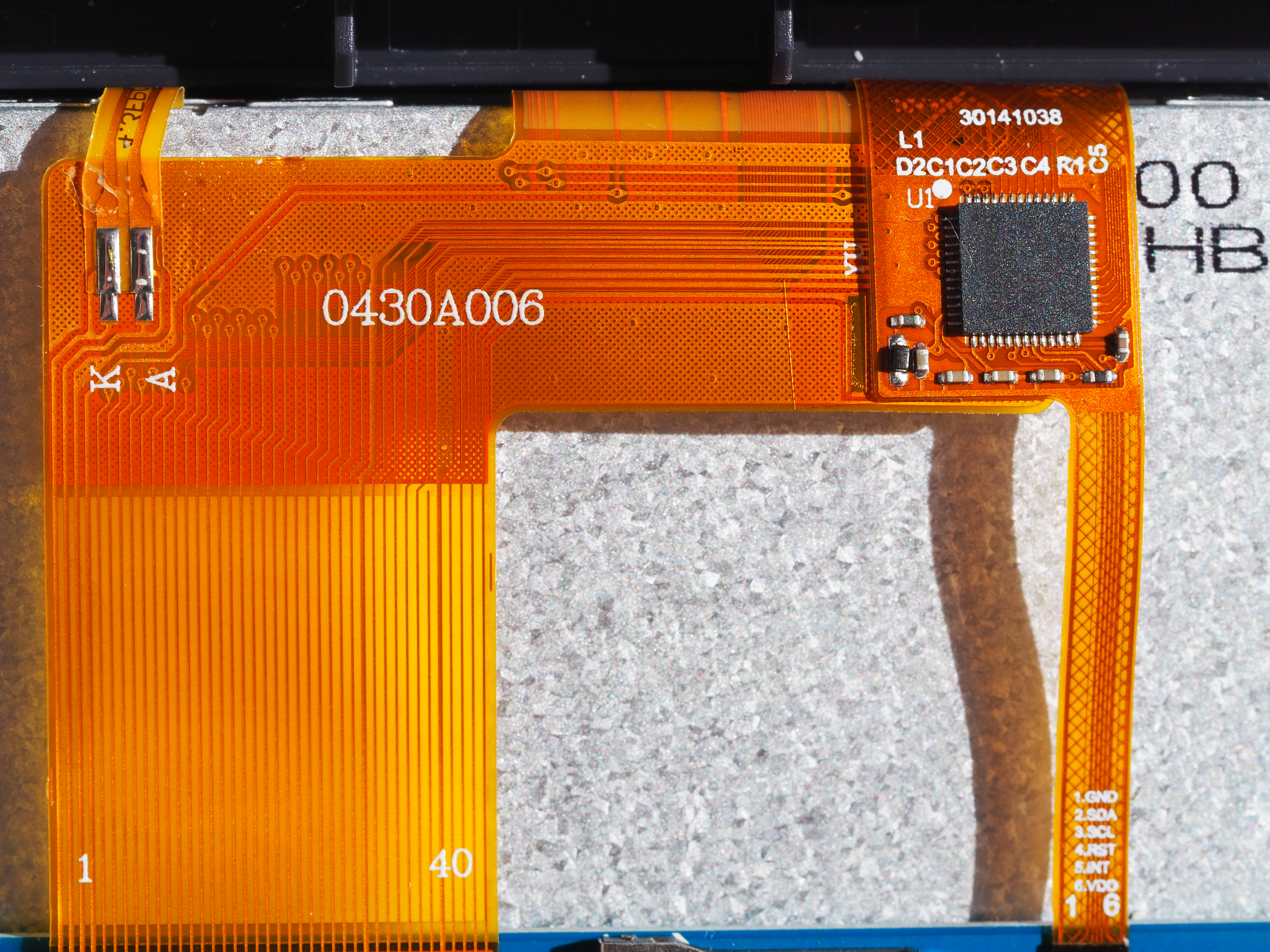
These specifications were taken from the Goodix website.
| Feature | Detail |
|---|---|
| Touch Points | 5 |
| Channels | 26Tx, 14Rx |
| Scren Size | ≤7” |
| Report Rate | 100Hz |
| Package | QFN52 |
| Chip Size | 6mm x 6mm x 0.8mm |
| Interface | I2C |
Hardware Hacking Notes
USB-C Port
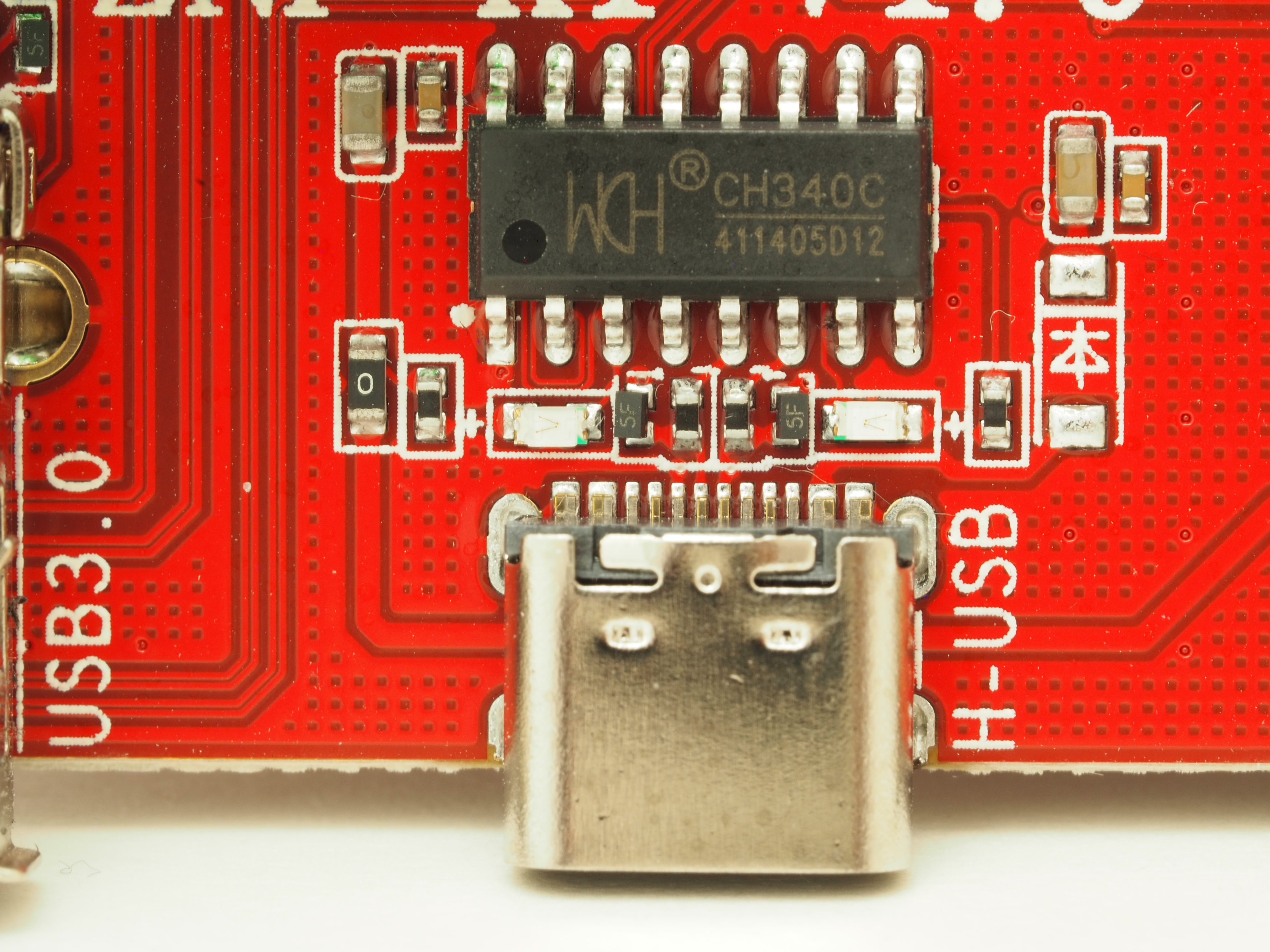
This is wired directly into a serial adapter, and can not be used as an actual USB port for the host. It will be accessible to the host on /dev/ttyS2.
This serial connection can be extremely helpful when SSH is not available, such as when needing to access the bootloader or an alternative OS. Connect at 5000000 baud.
USB 2.0 Header
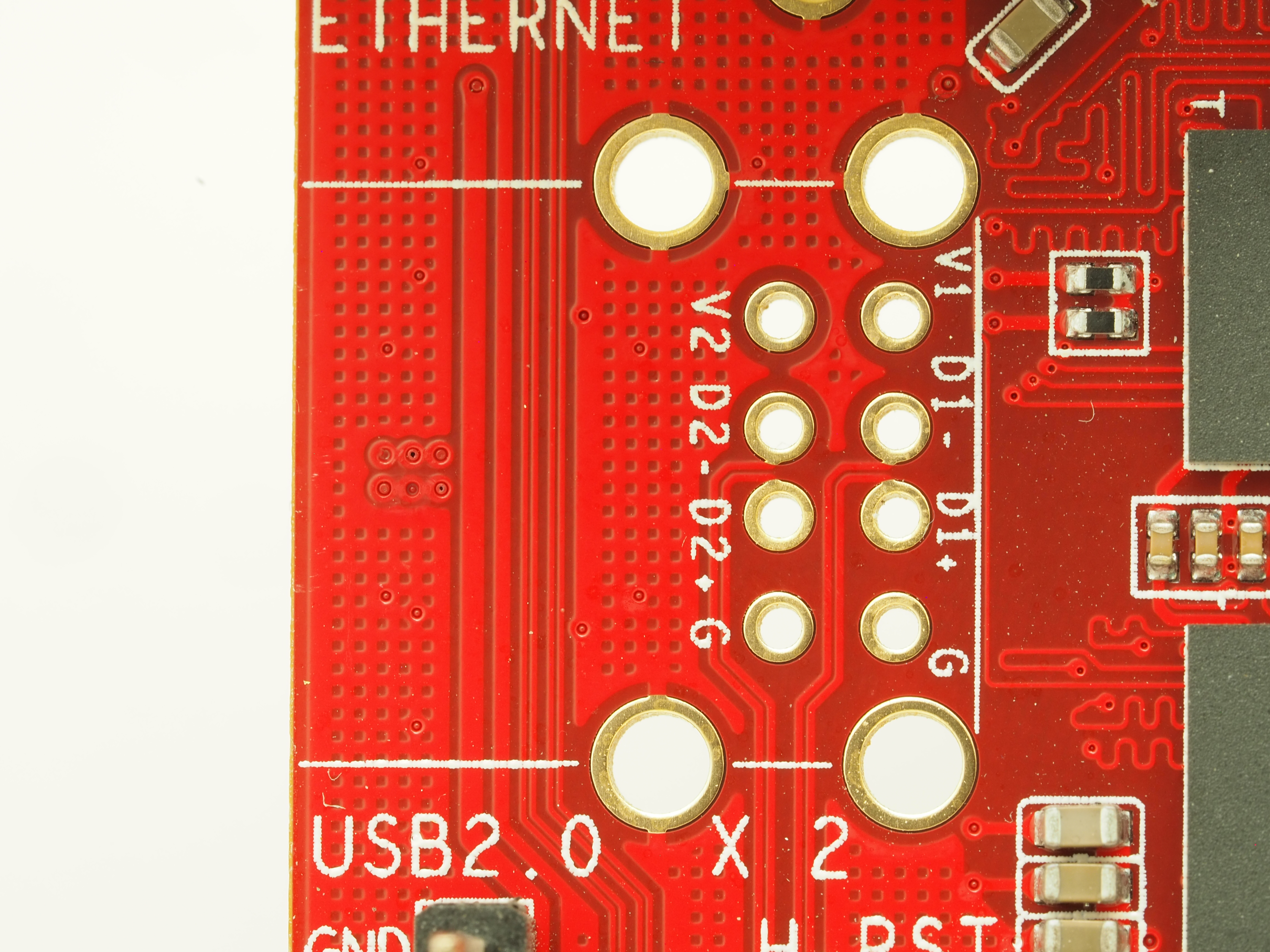
The unpopulated USB 2.0 header is connected to the host (not the MCU), and can be used for WiFi, additional storage, etc.
Unlike the USB 3.0 port, the USB 2.0 ports are visible to the uBoot bootloader, and can be used to boot from a USB drive. This can be helpful for trying out newer/different OS versions without wiping out the factory install.
ADXL345
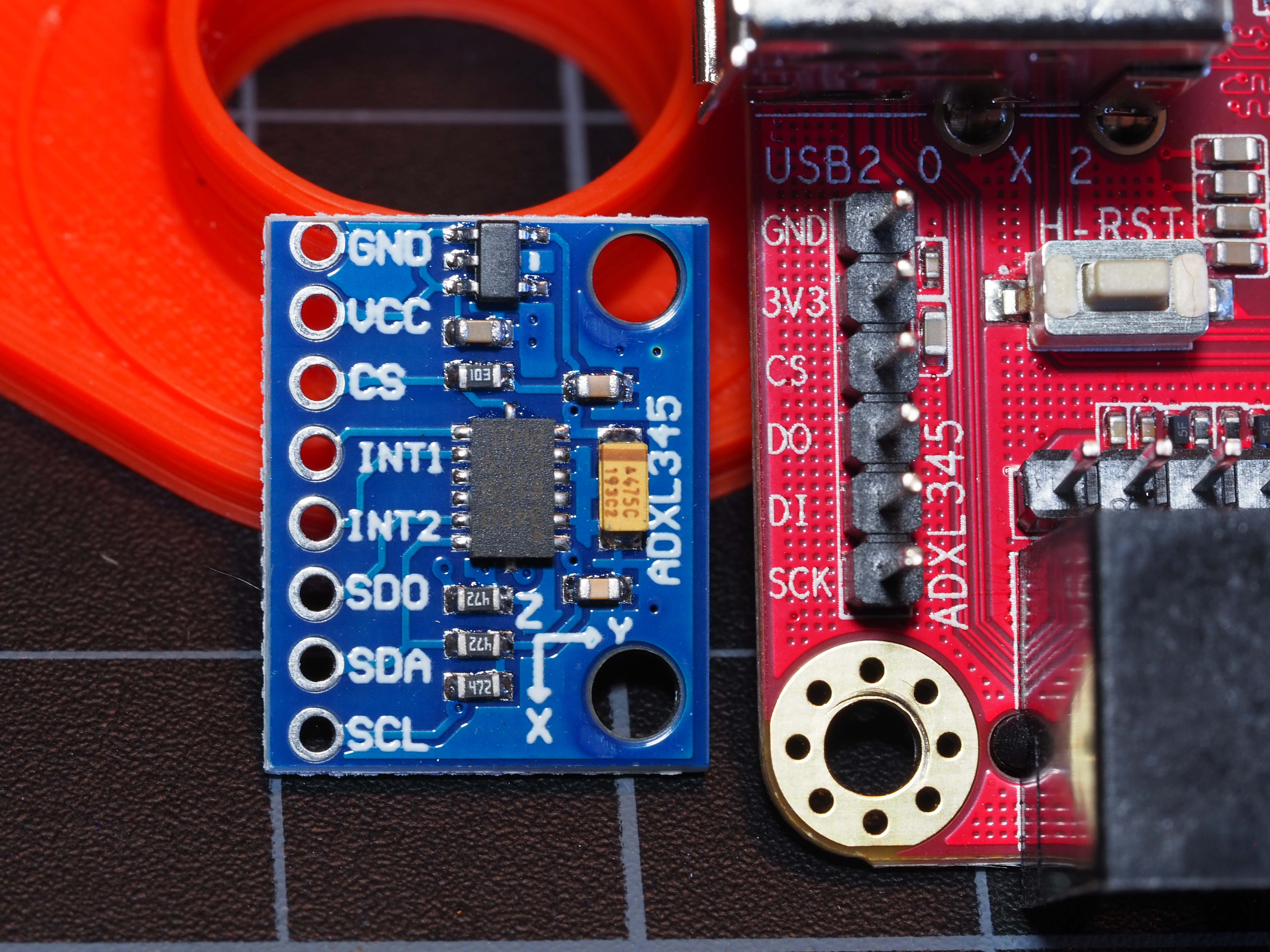
There is a dedicated header for an ADXL345 interface present, and appears to be connected to the host device. If this is the case, some straightforward configuration may be necessary.
MicroSD Reader
This only connects to the MCU and is primarily useful for updating the MCU firmware. It is currently unknown what filename scheme it uses to look for an update on the card. Based on other Elegoo models and similar boards, some possibilities include:
elegoo.binfirmware.bin- Any filename ending in
.bindifferent from the previous update.
Screen
Connecting to Non-Elegoo Klipper
This does not appear to be possible at the moment, without significantly more third-party software support. A number of open-source attempts have been started and abandoned for similar screens over the years. The complication mostly seems to be in the custom firmware these screens use and the unavailability of a helpful serial interface.
UART Connector
This connector is connected to the host (not the MCU), and is used to control the screen, but could be theoretically used to communicate with other UART devices. While it is possible to solder a header on to the board, it is safer to just make an RJ-11 adapter for debugging.
The header pinout is +5v GND TX RX. If wiring up an adapter, keep in mind that the TX pin is wired to the RX pin on the other device, and vice-versa.
MCU
Connecting
There does not appear to be any available serial or JTAG interface to connect directly to the MCU, except the microSD card reader. The host device connects to the MCU through an on-board hardware connection, using /dev/ttyS0.
BOOT0
In order to enter the firmware flashing interface, the MCU must be booted into BOOT0 mode. Once booted into this mode, it will attempt to flash firmware from an inserted microSD card or, if none is available, wait for communication over the serial connection.
There appear to be two ways to enter BOOT0.
The first, and safest, way is to set one GPIO pin high to signify entering BOOT0, and another to reset the MCU. Determining the exact pins is a work-in-progress.
The second, highly-unrecommended, way is to jump the two BOOT0 pads (notated as BOO in the diagram above) and press the reset button (see below). Due to close spacing on the board, it can be very easy to make unintentional contact with other components, causing significant damage.
Firmware
DO NOT UPGRADE THE MCU FIRMWARE WITH KLIPPER-GENERATED BIN!
It appears as though Elegoo has done something odd when generating their firmware, and the firmware generated by Klipper won’t work. Also note that the firmware generation settings in printer.cfg are absolutely incorrect, and were likely due to the config file being copy/pasted from a different printer model.
After some reverse-engineering, it appears as though Elegoo used the following .config file to generate the firmware file. However, this is not compatible with new versions of Klipper, and firmware files compiled using a newly-generated equivalent do not seem to work.
# Commmented-out options omitted
CONFIG_MACH_STM32=y
CONFIG_BOARD_DIRECTORY="stm32"
CONFIG_MCU="stm32f401xc"
CONFIG_CLOCK_FREQ=84000000
CONFIG_SERIAL=y
CONFIG_FLASH_START=0x800800
CONFIG_FLASH_SIZE=0x40000
CONFIG_RAM_START=0x20000000
CONFIG_RAM_SIZE=0x10000
CONFIG_STACK_SIZE=512
CONFIG_STM32_SELECT=y
CONFIG_MACH_STM32F401=y
CONFIG_MACH_STM32F4=y
CONFIG_HAVE_STM32_USBOTG=y
CONFIG_STM32_FLASH_START_8000=y
CONFIG_CLOCK_REF_FREQ=8000000
CONFIG_STM32F0_TRIM=16
CONFIG_STM32_SERIAL_USART1=y
CONFIG_SERIAL_BAUD=250000
CONFIG_USB_VENDOR_ID=0x1d50
CONFIG_USB_DEVICE_ID=0x614e
CONFIG_USB_SERIAL_NUMBER="12345"
CONFIG_CANBUS_FREQUENCY=500000
CONFIG_HAVE_GPIO=y
CONFIG_HAVE_GPIO_ADC=y
CONFIG_HAVE_GPIO_SPI=y
CONFIG_HAVE_GPIO_I2C=y
CONFIG_HAVE_GPIO_HARD_PWM=y
CONFIG_HAVE_GPIO_BITBANGING=y
CONFIG_HAVE_STRICT_TIMING=y
CONFIG_HAVE_CHIPID=y
CONFIG_HAVE_STEPPER_BOTH_EDGE=y
CONFIG_INLINE_STEPPER_HACK=y
Based on the above, the printer.cfg, similar boards, and the processor datasheet, the settings make menuconfig are probably close to the following:
| Setting | Value |
|---|---|
| Micro-controller Architecture | STMicroelectronics STM32 |
| Processor model | STM32F401 |
| Bootloader offset | 32KiB |
| Clock Reference | 8 MHz crystal |
| Communication interface | Serial (on USART1 PA10/PA9) |
| Baud rate for serial port | 250000 |
| GPIO pins to set at micro-controller startup | [blank] |
However, this does not seem to work. If you really want to try, it’s highly-recommended to first dump the existing firmware using stm32flash -r firmware_backup.bin /dev/ttyS0 while in BOOT0.
Missing/Unknown Components
This section does not include components detailed above, such as the USB-2.0 block, BOOT0 pads, etc.
Jumper Block
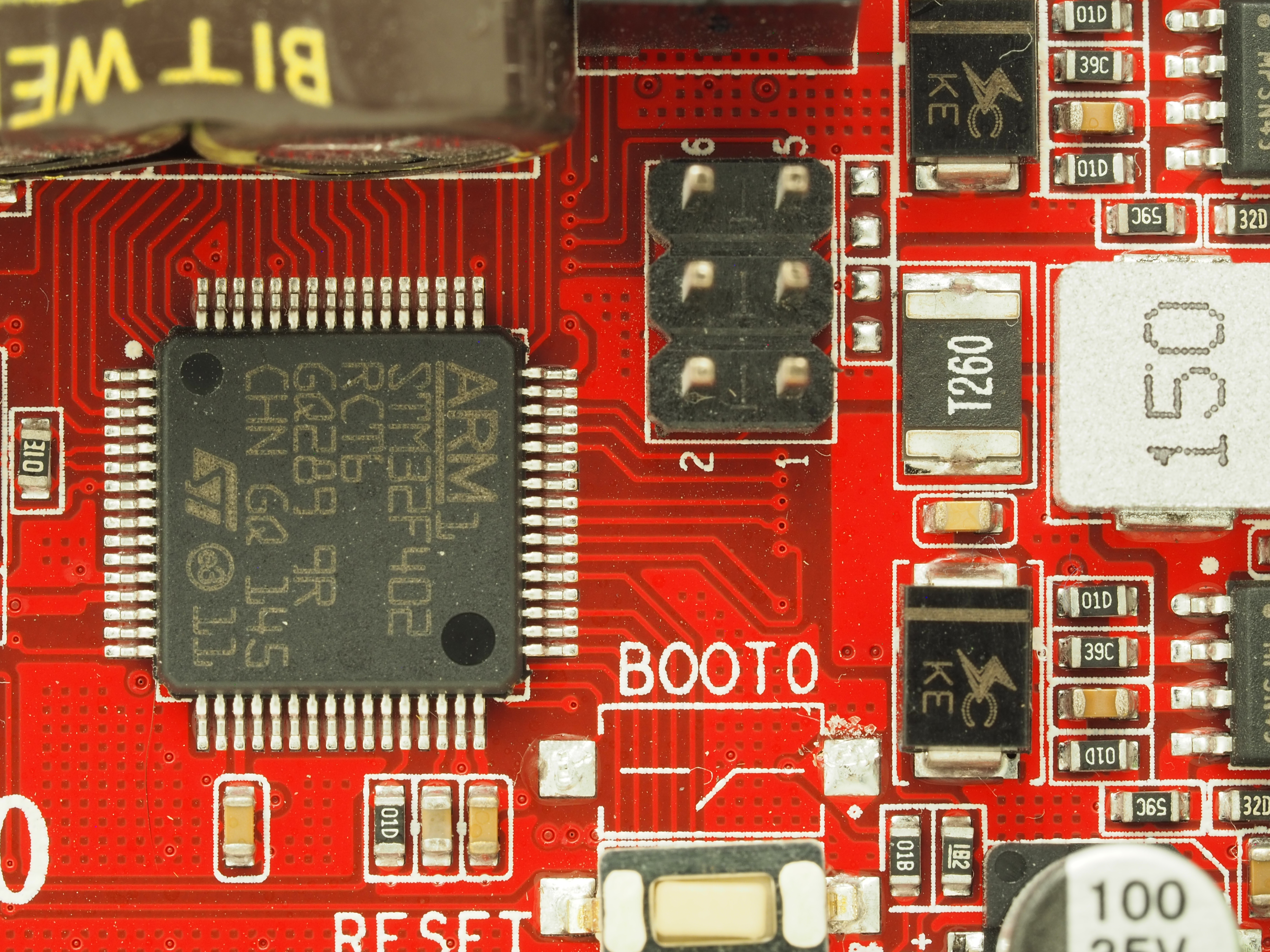
This jumper block’s purpose is currently unknown. It appears to be connected to the MCU and these unpopulated pads.
The pads appear to be the right shape, size, and configuration for resistors. This configuration (IC pin → jumper → resistor) is commonly used to configure features/settings on an IC. It may be that this is intended for features the board doesn’t currently support, but will be supported on future revisions.
With all the cost-saving measures they have taken with this board, it is curious that they bothered mounting the jumper pins, though. There may be some clues available in the MCU datasheet.
Empty Pads
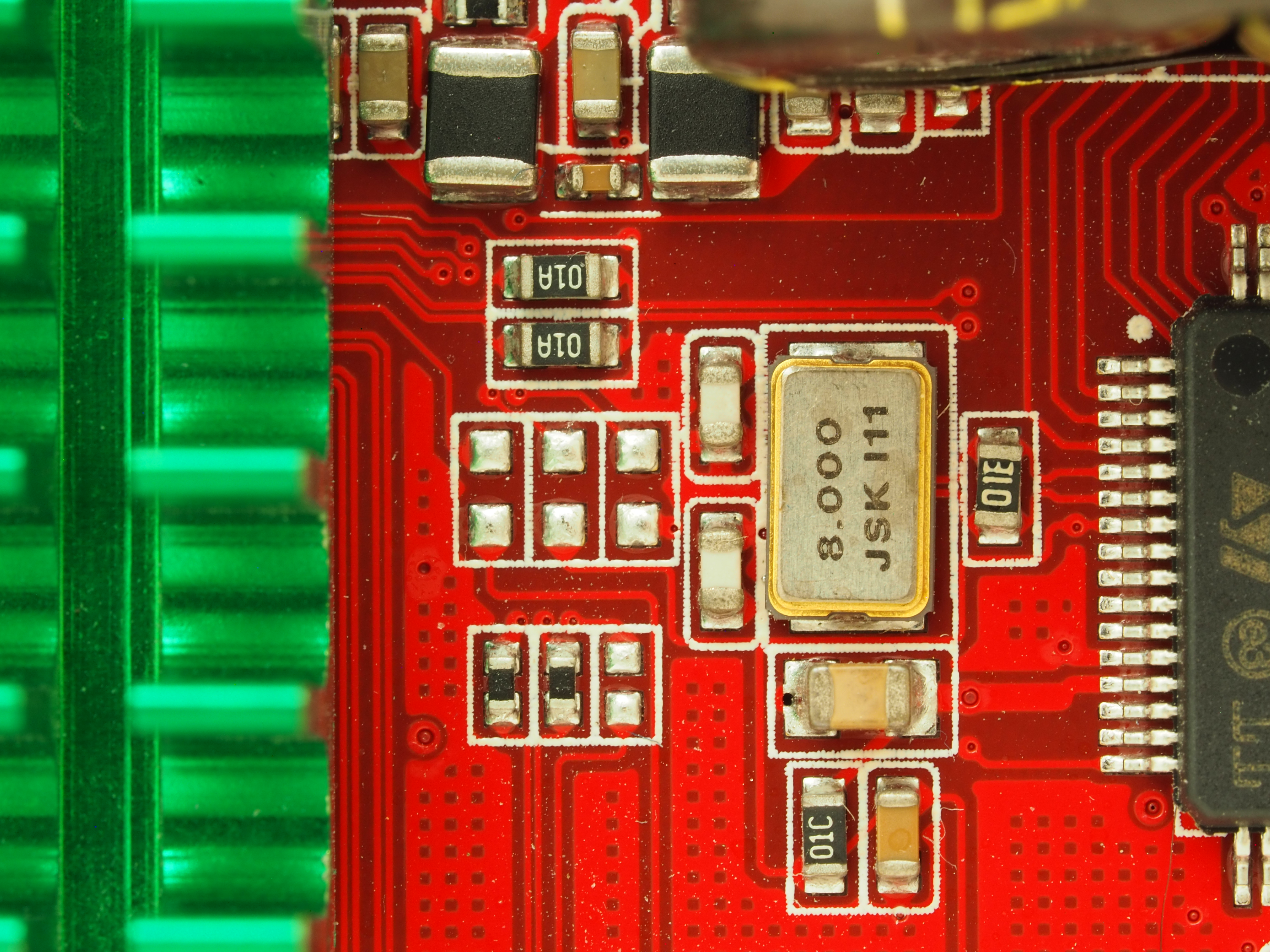
These pads appear to be directly connected to the host SoC and/or the MCU. It could be that these are intended to modify features/settings on one or both ICs.
A more interesting explanation is that these represent a disconnected interface between the two. This could be a second serial connection or a GPIO (or similar) pin that can be used to dynamically configure the MCU from the host.